 |  |
Build specifications
| Core specifications | - |
|---|---|
| Final weight (no payload, no motors) | 180 g |
| Fin thickness | 0.016" |
| Fin material | G10 fiberglass |
| Fin adhesive | DevCon 2-Ton epoxy |
| Body material | Blue Tube |
| Body adhesive (for bulkheads, couplers, mount points) | DevCon 2-Ton epoxy |
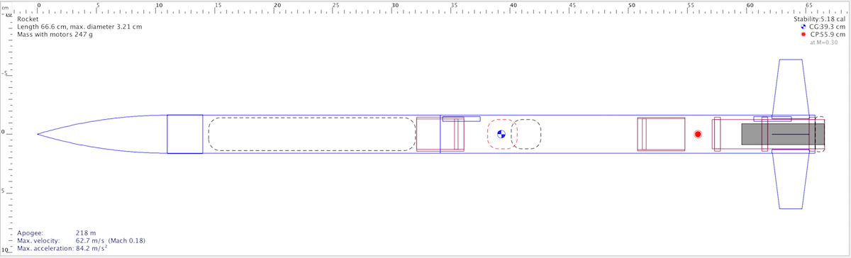
| CP (from nose) | 55.9 cm |
| Recovery method | single main parachute (18" thin-mil, attached via safety snap barrel swivel) |
| Recovery - Drogue trigger | N/A |
| Recovery - Main trigger | motor delay ejection |
| Recovery protection | Piston and Nomex sheet |
Flight specifications
| Aerotech a | - |
|---|---|
| Motor | |
| Launch weight | |
| Average thrust-to-weight ratio | |
| Predicted rail exit velocity (6ft rail) | |
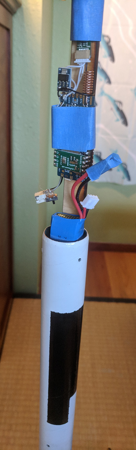
| Electronics | custom - telemetry (917MHz)/recording only (no flight operations) |
| CG (from nose) | |
| Stability |
Checklist
- motor
- motor assembled
- motor installed in fin can and retainer tight
- payload
- battery attached
- attach electronics to computer, erase flash
- detach electronics from computer, attach to sled
- electronics switch battery power on
- electronics sled installed in payload bay
- nosecone attached (3 screws)
- computer receiving and storing data
- computer displaying data
- handheld receiver preamp on
- handheld receiver displaying data updates
- recovery
- parachute opened and inspected
- lines even and untangled
- parachute folded, lines wrapped
- shock cord lightly wound and in tube
- parachute in tube
- Nomex sheet in tube
- piston moves smoothly in tube
- passes shake test
- launch prep
- igniter inserted and retained
- igniter attached to launch control
- computer receiving and displaying data updates
- handheld receiver displaying data updates
- launch
- post-recovery
- handheld receiver displaying data updates
- remove nosecone (3 screws)
- turn off electronics
- download full data to computer
Design
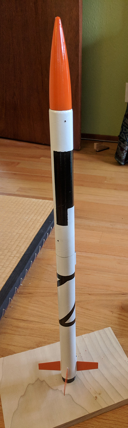
Custom design, modified from Sunrise. This rocket was created to be a robust, general-purpose test bed for telemetry electronics testing.
 |
It consists of two sections - an aft section with the motor mount, fins, and recovery bay, and a forward payload section.
 |
The motor mount is 24mm and has a threaded retainer, to allow flights with both 18mm and 24mm motors. There is a piston to protect the recovery bay from ejection gasses.
The nose cone is held to the payload section with 3 4x40 set screws (flush with the outside of the rocket).
 |  |
Update after first two flights: After the piston failed to entirely protect the parachute in the second flight, a nomex sheet was also added. Unfortunately, the blue tube couplers fit loosely in the body tube - leading to a small gap that sometimes (but not always it appears) allows some hot ejection gasses past the piston. This could probably be fixed in the future by applying some epoxy or CA to the outside of the piston and then sanding it back down to a proper fit.
Construction
Fins, piston, and motor mount
The fins were layed out on a sheet of G10 (0.016" thick) and cut out with a diamond-coated tile saw in a small rotary tool. They were trimmed and airfoiled with small file:
 |
The fins rest between the middle and aft centering rings on the motor mount. The locations of the centering rings were marked on the motor mount tube. The fins were epoxied to the motor mount tube using a custom laser-cut alignment guide. After the alignment guide was removed, epoxy fillets were applied to both sides of each fin along the entire root.
 |  |
A length of blue tube was used for the aft tube and notched on a bandsaw (the blade’s kerf was a perfect match for the thickness of the fins). The notches extend all the way to the aft end of the tube to facilitate easier assembly — because there was little room between the motor mount tube and the aft section tube epoxy internal fillets would not be possible after the motor mount was attached inside the aft tube. So the entire motor mount with fins already attached was slid into the end of the tube.
 |
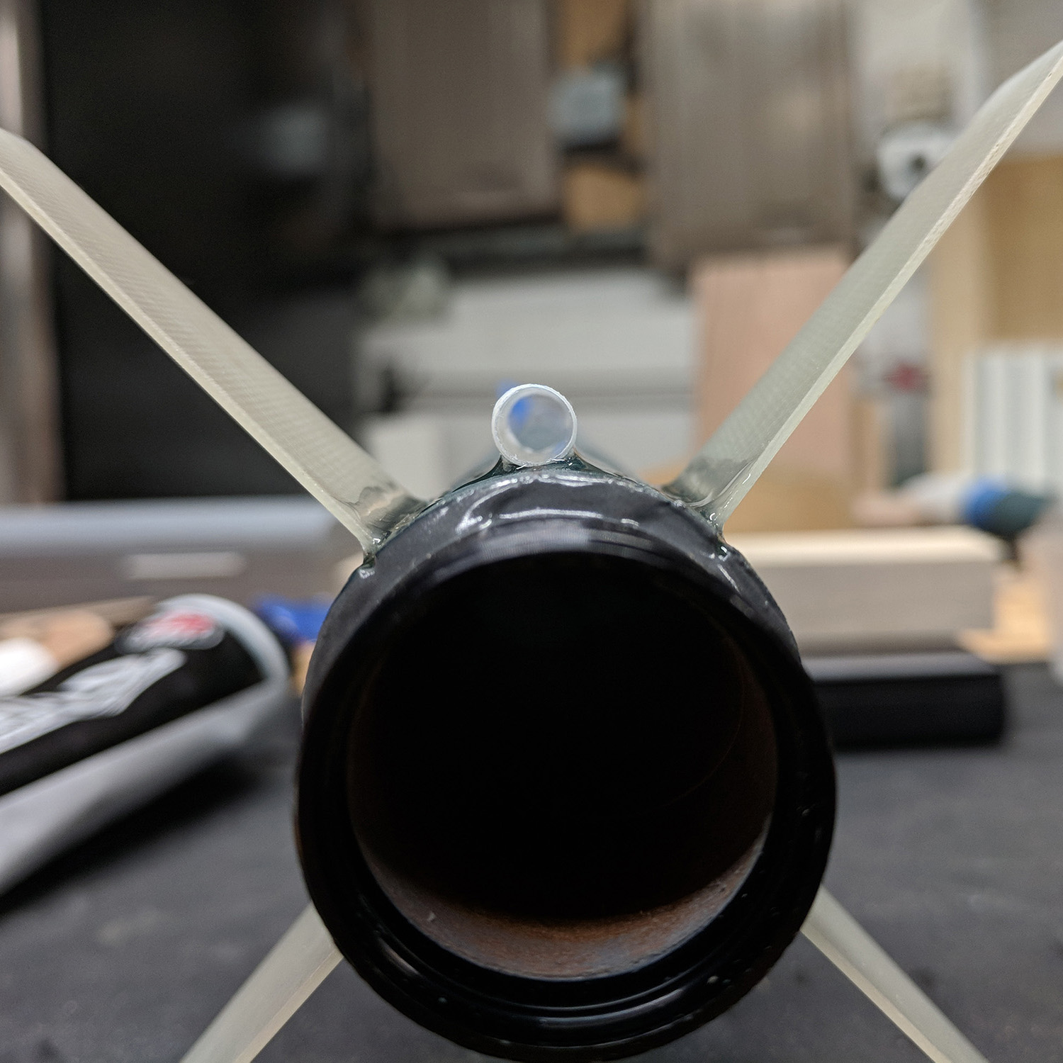
A short section of coupler tube was used to create the piston. A short length of kevlar shock cord was wrapped around a washer and threaded through a slot in the bulkhead for the piston. The washer and the end of the shock cord were epoxied to the bulkhead, a liberal amount of epoxy was used to ensure that the bulkhead was sealed against exhaust gasses. The bulkhead was then epoxied with fillets on both sides into the coupler tube.
 |  |
The other end of the piston shock cord was threaded underneath the forward and middle centering rings, and all three centering rings were epoxied onto the motor mount tube. The shock cord was wrapped in blue tape to protect it from epoxy. A line of epoxy was put into the aft tube just below the depth of the forward centering ring. As the motor tube/fin assembly was pushed into the aft tube, additional epoxy was applied to each centering ring (outside, forward, rear) ensure that there would be a bond between each centering ring and the aft tube, and at least some fillet would form on each centering ring.
 |  |
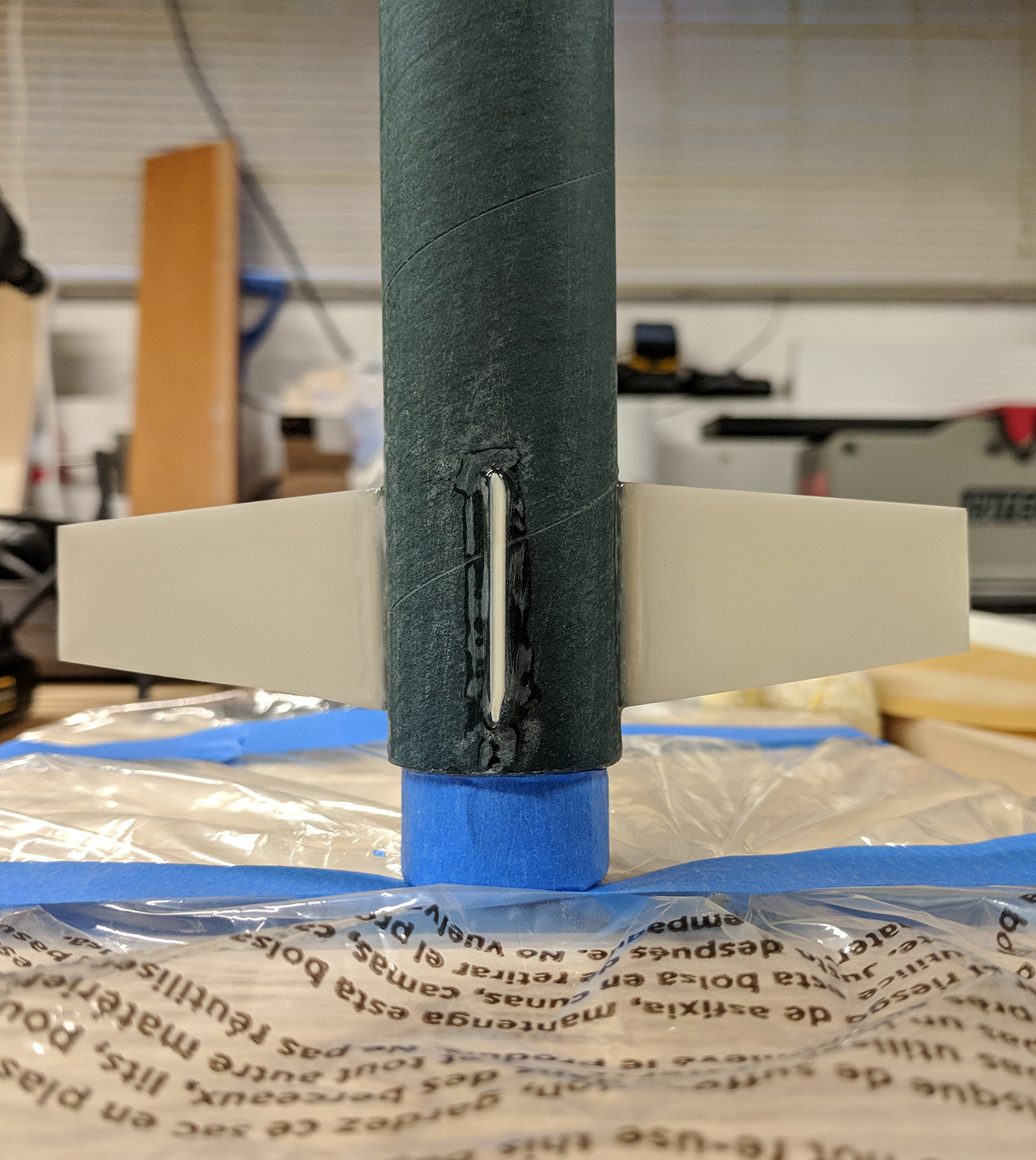
Additional epoxy fillets were added to the fins on the exterior of the aft tube. An epoxy fillet on the aft end of the aft centering ring was also added, and the gaps in the notches at the end of the tube were filled in with epoxy.
 |  |
The motor retainer was attached with JB Weld high-temperature epoxy (since it is metal and conducts heat from the motor). 3/16" launch lugs were epoxied on while held with tape, then fillets were added to their sides.
 |  |  |
Payload section
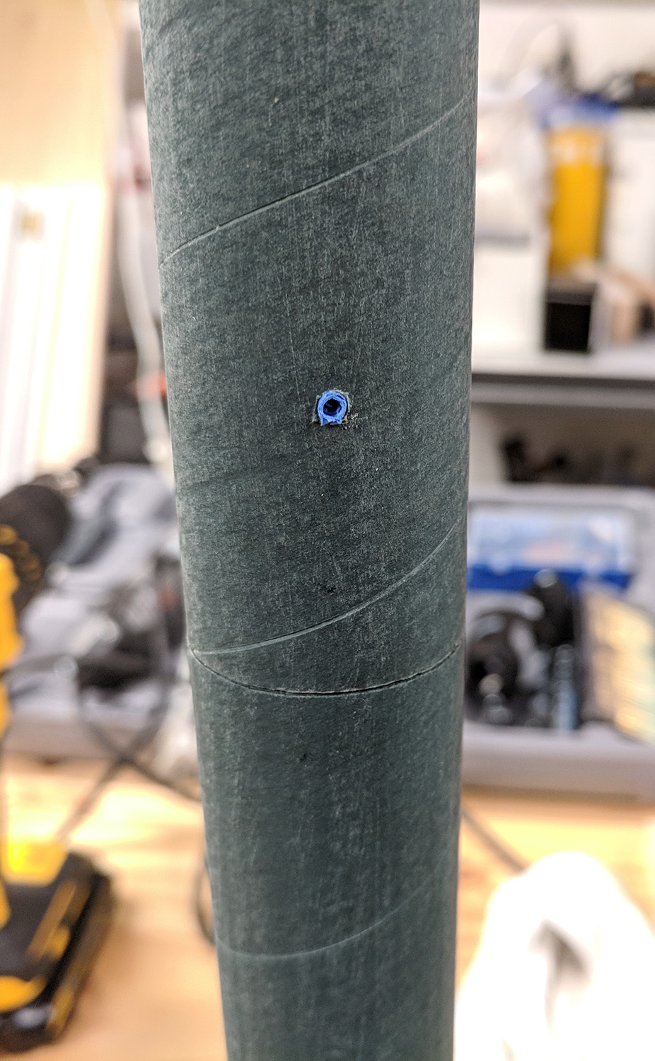
A length of blue tube was used for the payload section. It has 3 holes drilled and tapped for 4x40 set screws at the forward end (to hold the nose cone on during flight).
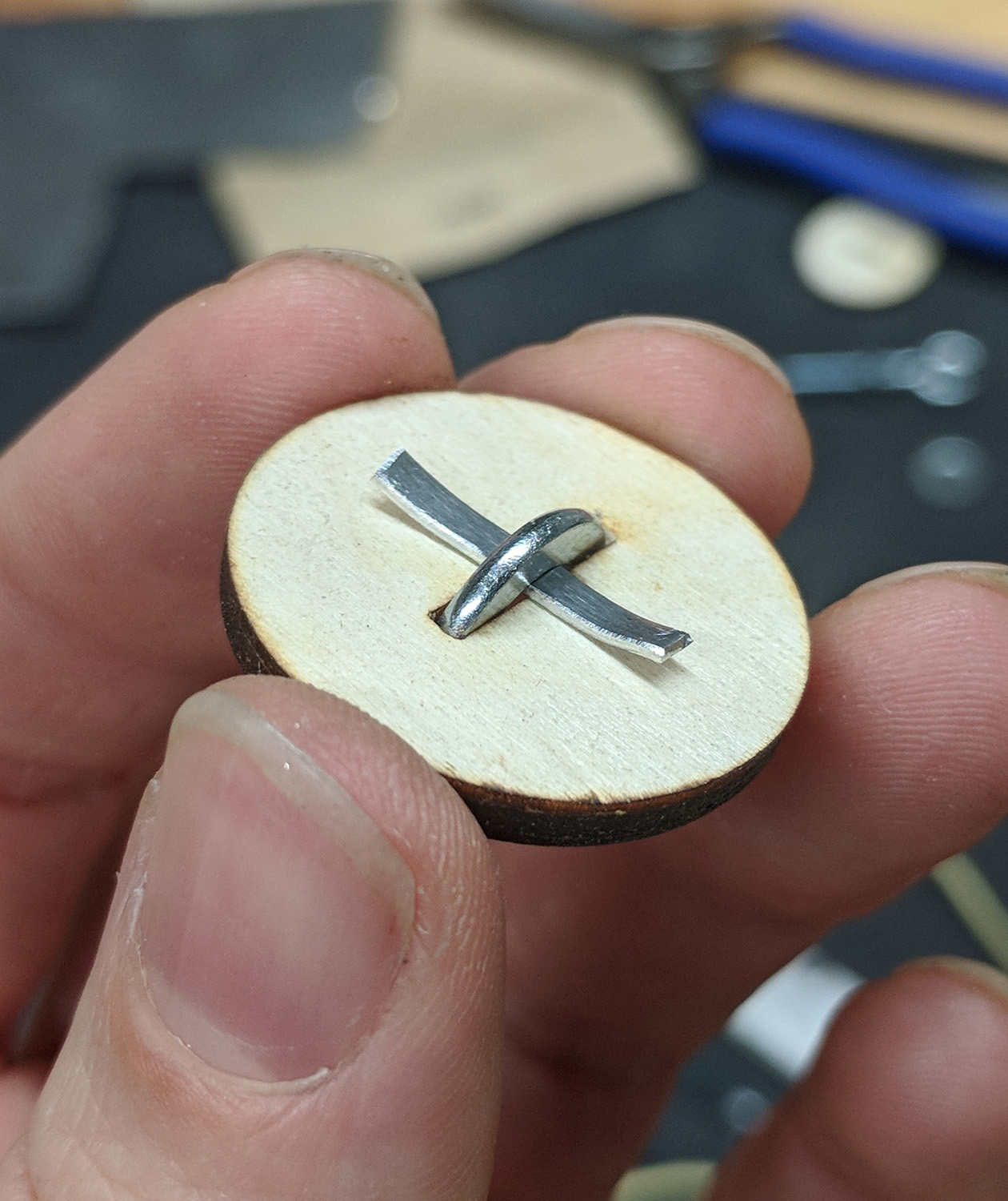
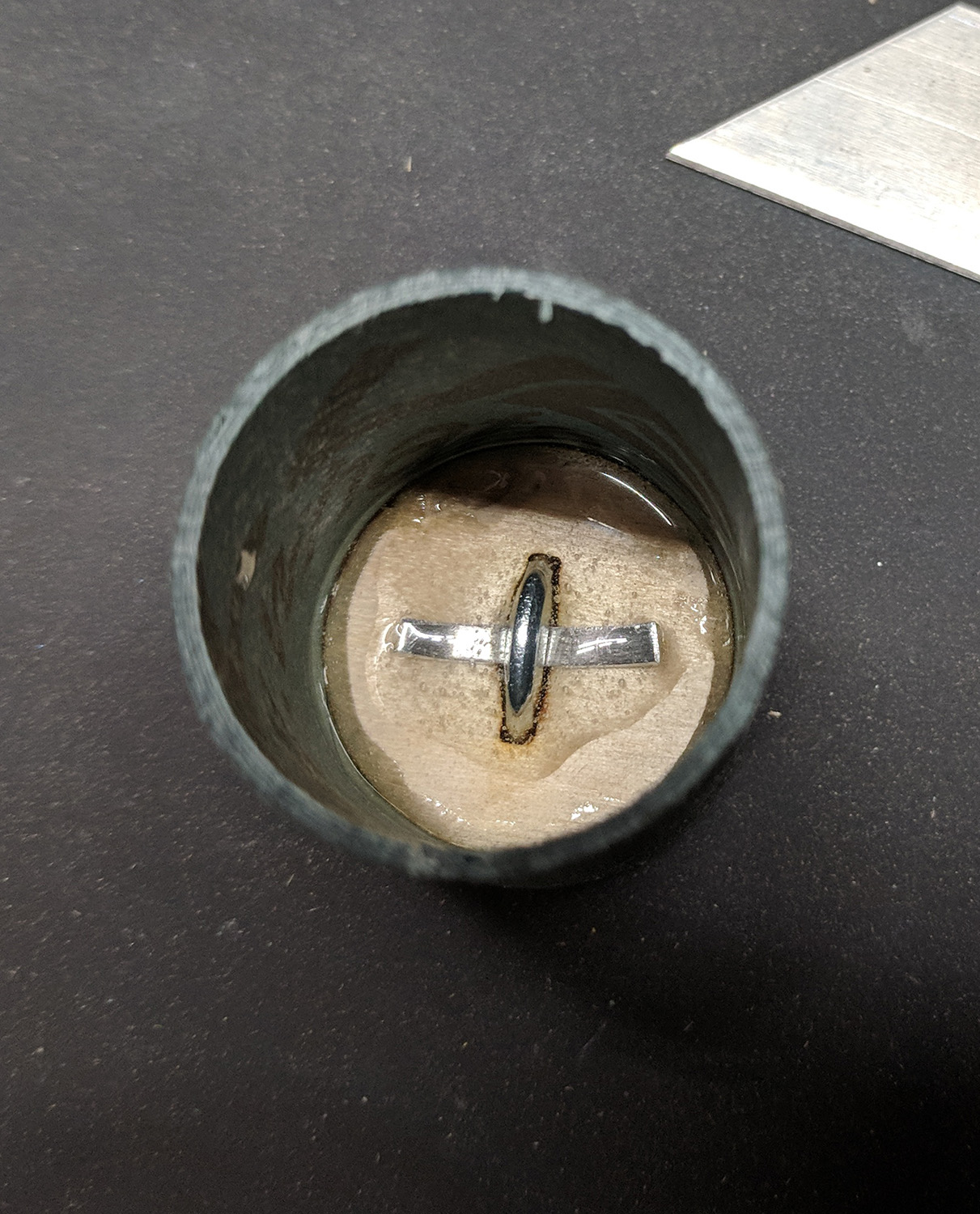
A bulkhead with a slot was epoxied into the forward end of the piston. Because there were no good small eyebolt options, a small strip of aluminum was used to secure a washer in the slot in the piston. Epoxy was liberally applied to the slot and across the aluminum strip to both secure the washer and ensure that the bulkhead was sealed against ejection gasses. This bulkhead was then epoxied into the aft end of a tube coupler, with fillets on both sides.
 |  |  |
The tube coupler had a loose fit in the payload tube, so two strips of paper were epoxied to the coupler, sanded for a proper fit, and then the coupler was epoxied into aft end of the payload tube.
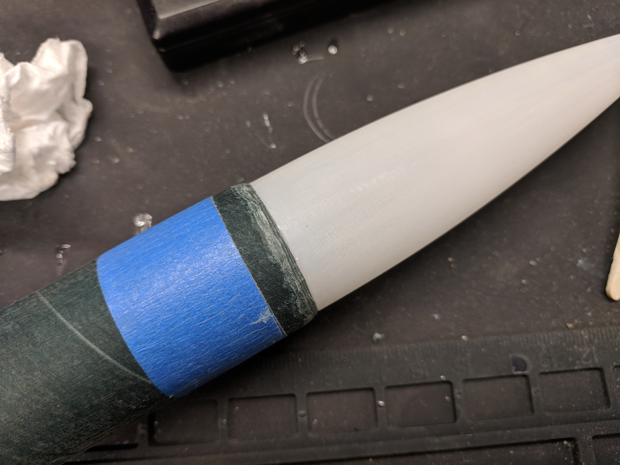
The only hollow nose cone options available at the time did not have a large enough diameter to be flush with the outside of the tube. The top of the payload tube was sanded to create a short transition between the tube and the nosecone. It was kept short to ensure that the tube was not too thin where the screws for the nosecone were placed.
 |
Painting
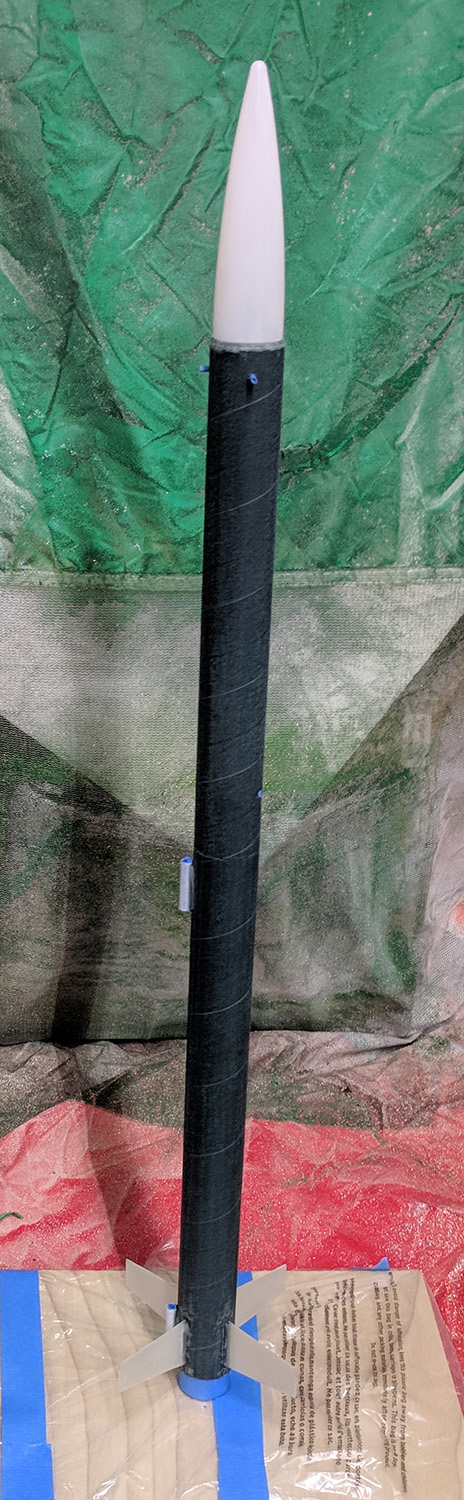
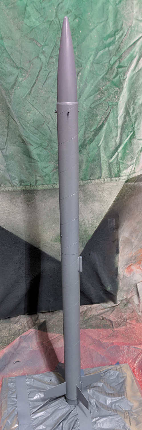
The rocket went through multiple stages of masking and painting. First a base coat of grey primer was applied to the entire rocket.
 |  |  |  |
Then the nose was masked and white was applied to all of the body tubes.
 |
Then it was wrapped and masked to apply orange to the nose cone and fins.
 |  |  |
The payload and aft sections were separately re-masked for the test pattern (inspired by the patterns used by the NASA Ares and Saturn rockets) and painted with black.
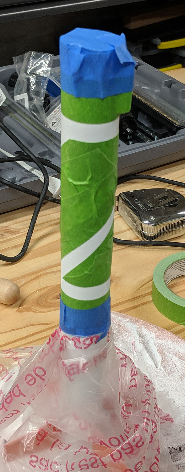 | 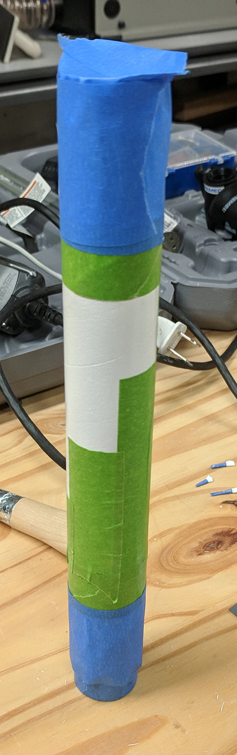 | 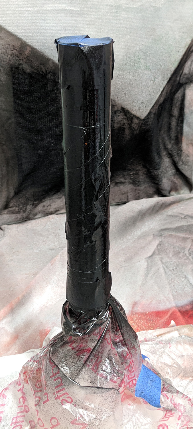 |
Finally, many clear gloss coats were applied to the entire rocket to provide a protective coating.
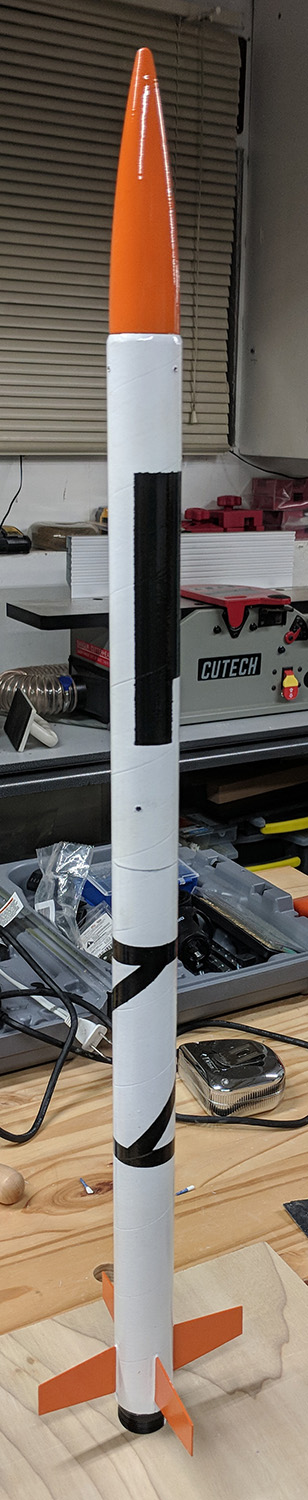 |
Shock cord, parachute, and assembly
The shock cord is 4x the rocket body length (for a total length of 265cm), has #5 safety snap barrel swivels (28lb test) on both ends, and a butteryfly knot loop 1/3 of the way from the forward end for attaching a parachute.
The parachute is attached with a safety snap barrel swivel to the loop. The shock cord’s ends are attached to the washers on the piston and payload section bulkheads.
The piston is first put into the aft tube. Then most of the shock cord is wound loosely and wrapped in the nomex sheet and put into the aft tube. The parachute is folded, lines wrapped around it, and put into the tube. Finally, the payload section’s coupler is inserted into the tube.
 |  |  |  |  |