 |
Build specifications
| Core specifications | - |
|---|---|
| Final weight (no payload, no motors) | 304 g |
| Fin thickness | 0.031" |
| Fin material | G10 fiberglass |
| Fin adhesive | West Systems 105 / 205 epoxy |
| Body material | Blue Tube |
| Body adhesive (for bulkheads, couplers, mount points) | West Systems 105 / 205 epoxy |
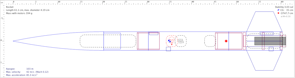
| CP (from nose) | 47.7 cm |
| Recovery method | single main parachute (18" thin-mil, attached via safety snap barrel swivel) |
| Recovery - Drogue trigger | N/A |
| Recovery - Main trigger | motor delay ejection |
| Recovery protection | Nomex sheet |
Flight specifications
| Aerotech a | - |
|---|---|
| Motor | |
| Launch weight | |
| Average thrust-to-weight ratio | |
| Predicted rail exit velocity (6ft rail) | |
| Electronics | custom - telemetry (917MHz)/recording only (no flight operations) |
| CG (from nose) | |
| Stability |
Checklist
- motor
- motor assembled
- motor installed in fin can and retainer tight
- payload
- battery attached
- attach electronics to computer, erase flash
- detach electronics from computer, attach to sled
- electronics switch battery power on
- electronics sled installed in payload bay
- nosecone attached (4 screws)
- computer receiving and storing data
- computer displaying data
- handheld receiver preamp on
- handheld receiver displaying data updates
- recovery
- parachute opened and inspected
- lines even and untangled
- parachute folded, lines wrapped
- shock cord lightly wound and in tube
- parachute in tube
- Nomex sheet in tube
- fin can inserted into main tube
- passes shake test
- launch prep
- igniter inserted and retained
- igniter attached to launch control
- computer receiving and displaying data updates
- handheld receiver displaying data updates
- launch
- post-recovery
- handheld receiver displaying data updates
- remove nosecone (4 screws)
- turn off electronics
- download full data to computer
Design
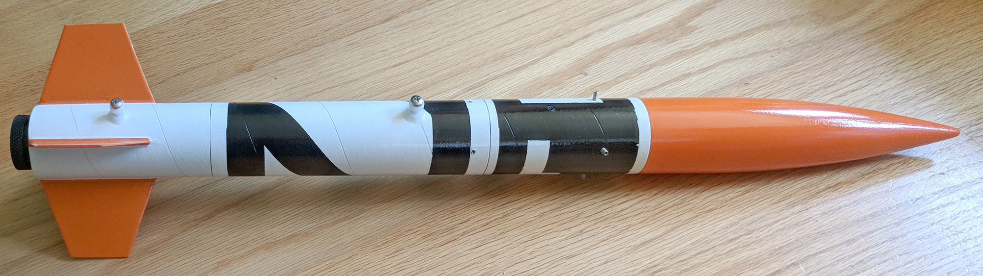
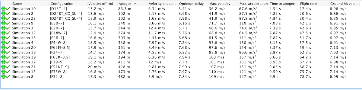
Custom design, based on learnings from the Intrepid 1. This rocket was created to be a robust, general-purpose test bed for telemetry electronics testing that is shorter and wider than the Intrepid 1. This gives more flexibility in payload size and shape, and more room for alternate recovery systems. The Intrepid 1 had the disadvantage that only two general motor options were available that kept it in stable flight while under the 1500ft low-power ceiling — a high-Ns C or a mid-Ns D. The Intrepid 2’s additional width provides just enough incremental drag that it enables a wider range of motor options that result in useful altitude steps that keep it under the 457m (1500ft) low-power ceiling — 85m (D15T), 100m (D24BT), 240m (E30/E20), 300m (E28), 340m (F44W), 370m (F62FJ/F24), 400m (F63R, F39), 430m (F51NT).
 |
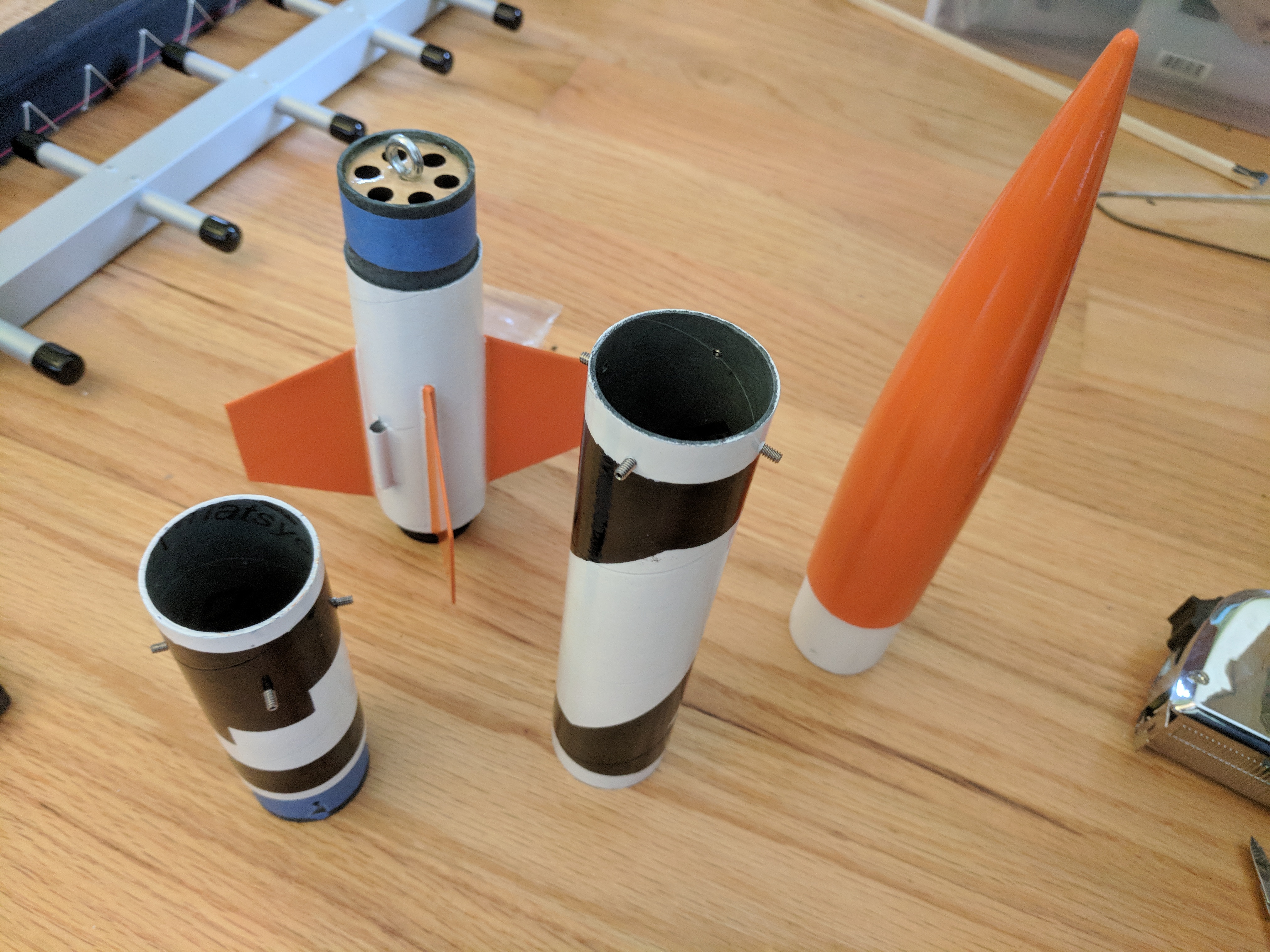
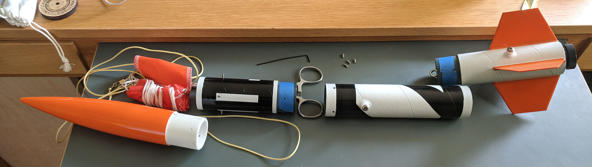
The design is intended to be modular, allowing for easy repair and replacement of sections with alternate experimental sections (e.g. payload section with window for camera):
 |
The motor is held in a fin can that is only as long as necessary for the motor mount, which has a forward bulkhead with an eye bolt and exhaust holes (for motor ejection charge separation). The recovery section separates from the fin can during flight, but is just a plain tube (the payload bulkhead is affixed to the payload section). It is firmly attached to the payload section’s bulkhead by four 4x40 set screws that are screwed in flush with the outside of the rocket (holes in blue tube can be threaded). The payload section is enclosed by a solid bulkhead at its aft (permanently attached with epoxy) and the nose cone (held on during flight with 4 more 4x40 set screws).
 |
The current fin can was created for flying 18mm and 24mm motors and has a 24mm motor mount in it, with a screw-on motor retainer. The motor mount is epoxied to the exterior tube with three laser-cut centering rings, and the fins are through-the-wall epoxied to the motor mount and the exterior tube.
There are future plans for a fin can for 29mm motors, which will be made longer to accommodate L1-cabable motor cases.
Construction
Fins
The fins were layed out on a sheet of G10 (0.031" thick):
 |
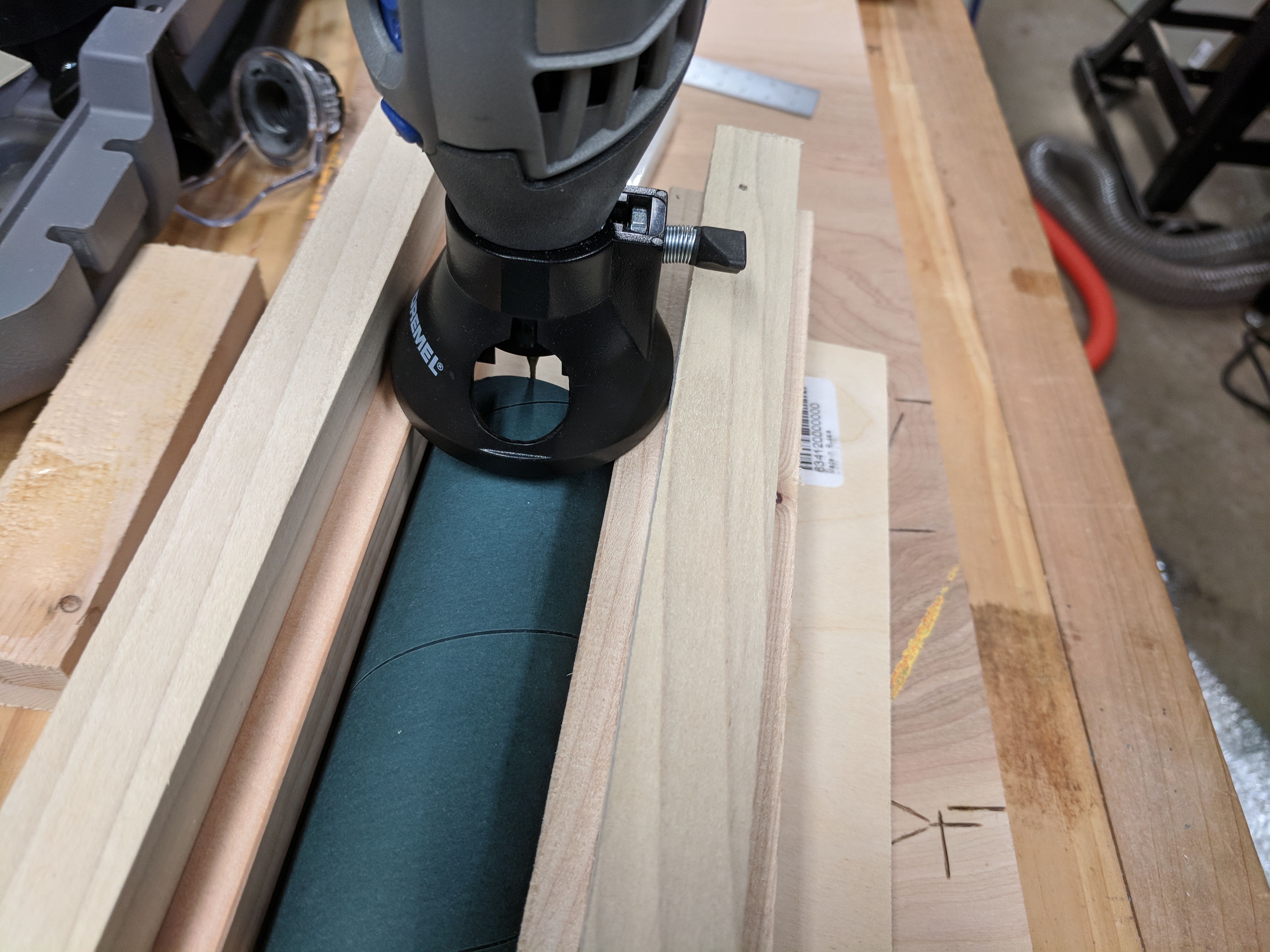
They were cut out with a diamond-coated tile saw in a small rotary tool, and trimmed and airfoiled with a sanding cylinder in the rotary tool:
 |
The aft of the fin root rests against the aft centering ring, the front of the fin root has a notch to go over the forward centering ring, and there is a notch in the middle to fit over the middle centering ring.
Fin can
The fin can is a section of blue tube that was notched for the fins in a custom jig using an end mill bit in a small rotary tool:
 |
The notches extend all the way to the aft end of the tube to facilitate easier assembly. The gaps left at the end of the tube are over the aft centering ring and are filled with epoxy when the aft centering ring is attached.
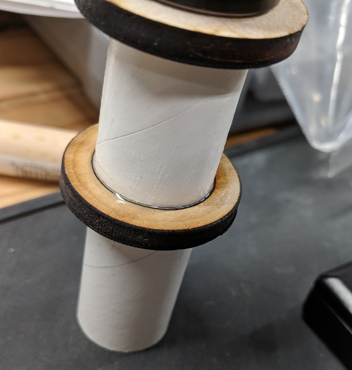
The middle centering ring was epoxied to the motor mount tube, then epoxied into the fin can (the forward and aft centering rings were temporarily placed on the motor mount tube to keep it centered while the epoxy set):
 |  |
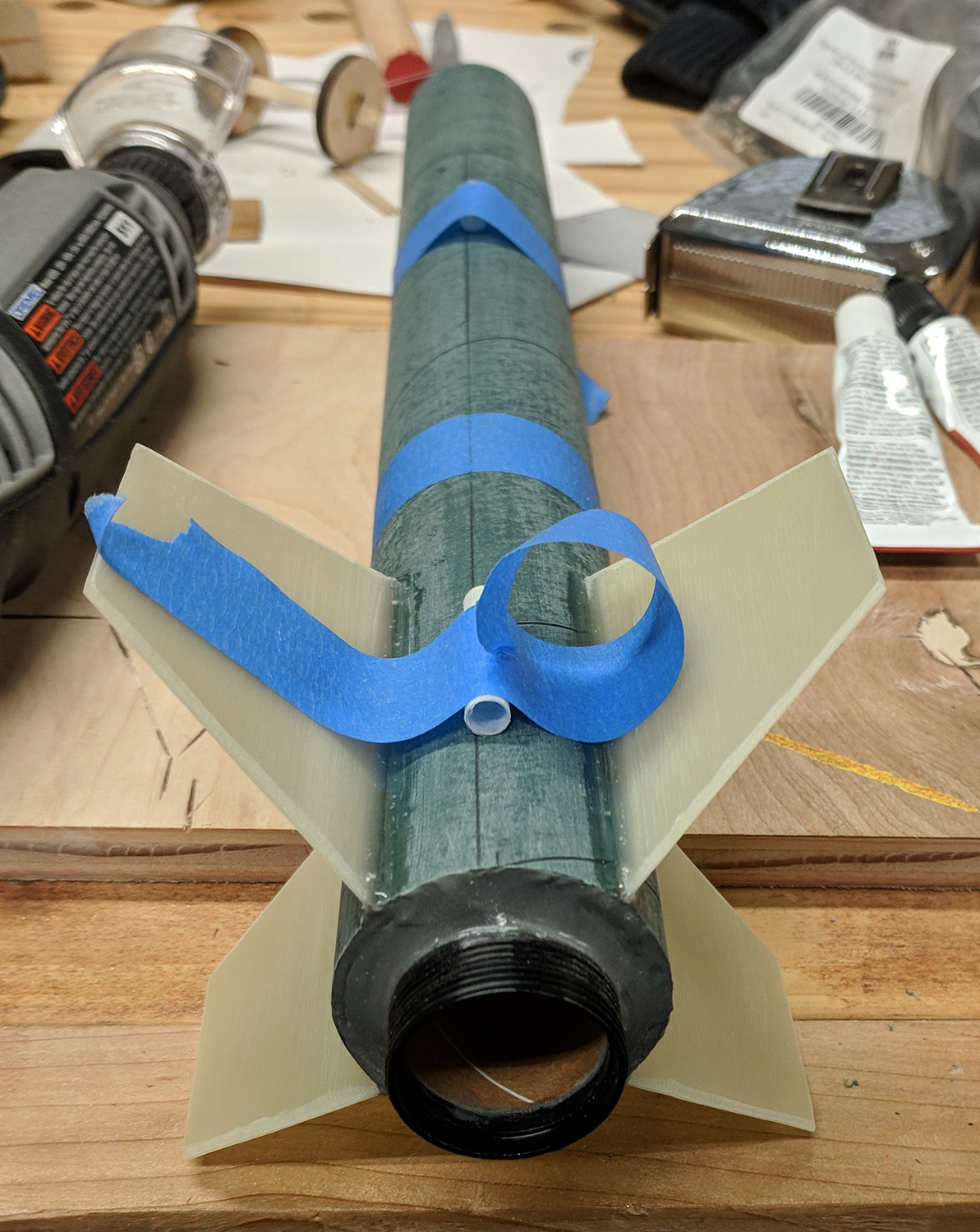
The fins were then attached, with epoxy fillets on the motor mount tube and interior and exterior the fin can:
 | 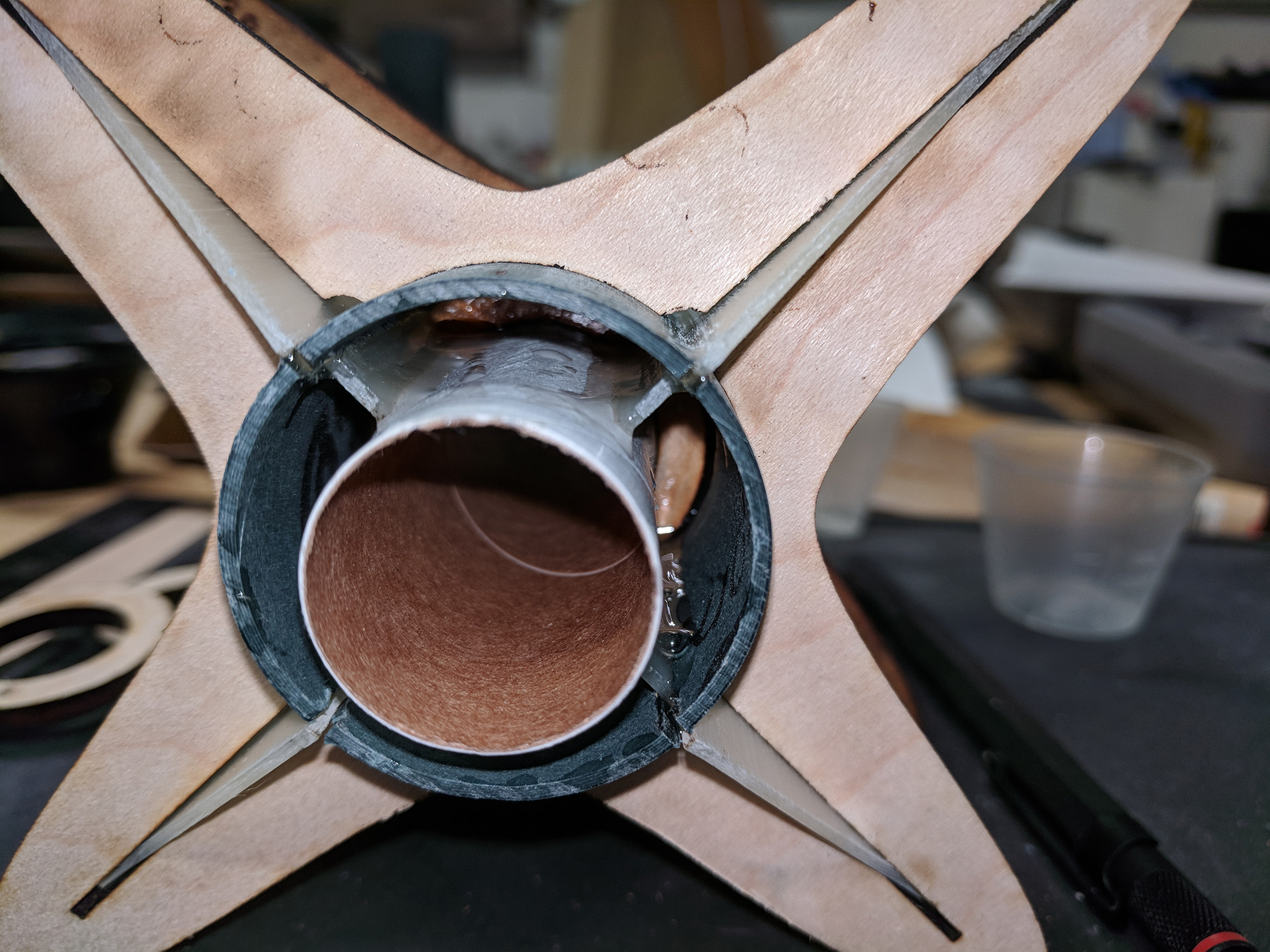 |  |
A tube coupler was prepared for the top of the fin can. A forward bulkhead is epoxied to the couple, with an eye bolt and exhaust holes (to allow the ejection charge to separate the fin can from the rest of the rocket). The eye bolt is held to the bulkhead with both a nut and epoxy. The coupler was slightly loose in the fin can, so CA was applied around the mating surface and then sanded to allow for a more precise fit while epoxying to the fin can.
 |  |
The forward and aft centering rings were epoxied into the fin can, and later the coupler was epoxied to the forward end of the fin can. A threaded motor retainer was epoxied to the aft end of the fin can. Because the retainer conducts heat well, JB Weld high-temperature epoxy was used.
 |  |
Recovery and payload sections
The recovery section consists of only a section of blue tube, with four holes drilled and tapped for 4x40 screws at the forward end.
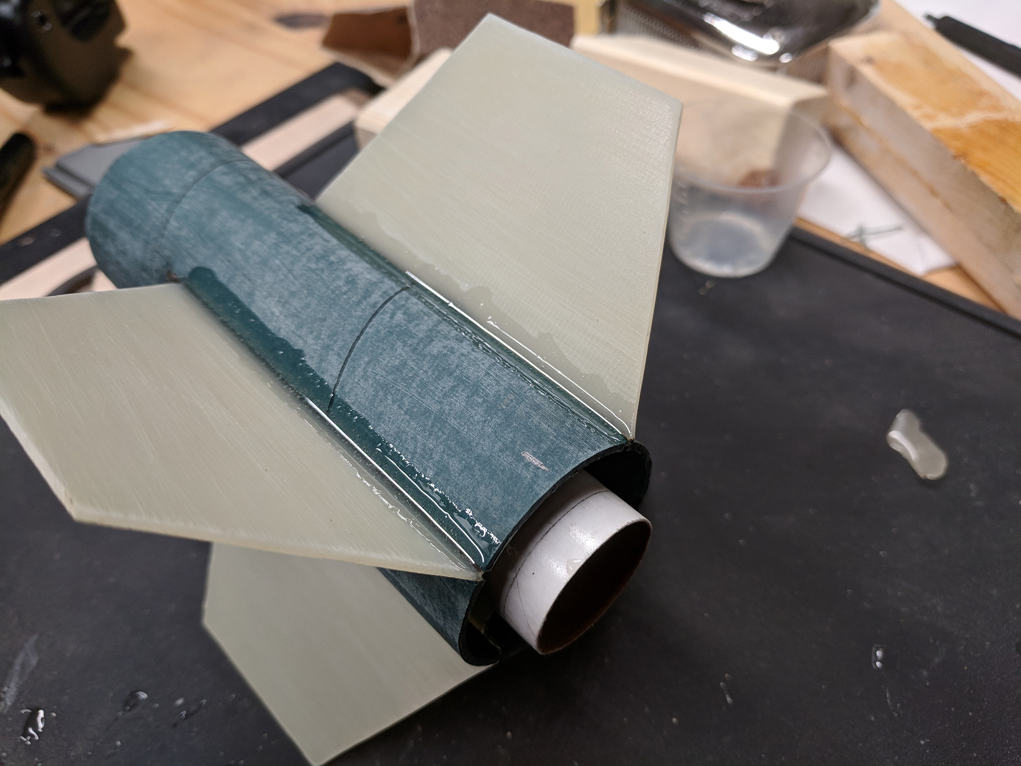
The payload section was made of a short section of blue tube, with four holes drilled and tapped for 4x40 screws at forward end (to attach the nose cone). There is a bulkhead attached to a tube coupler at the aft end of the payload section. The bulkhead is attached with epoxy fillets to the coupler and has an eye bolt facing aft, attached with both a nut and epoxy. The epoxy on the nut inside of the coupler was applied liberally to ensure that the bulkhead prevents any ejection gasses entering the payload section.
 |  |  |
Launch hardware
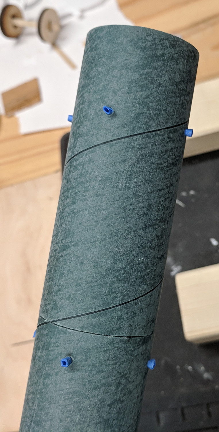
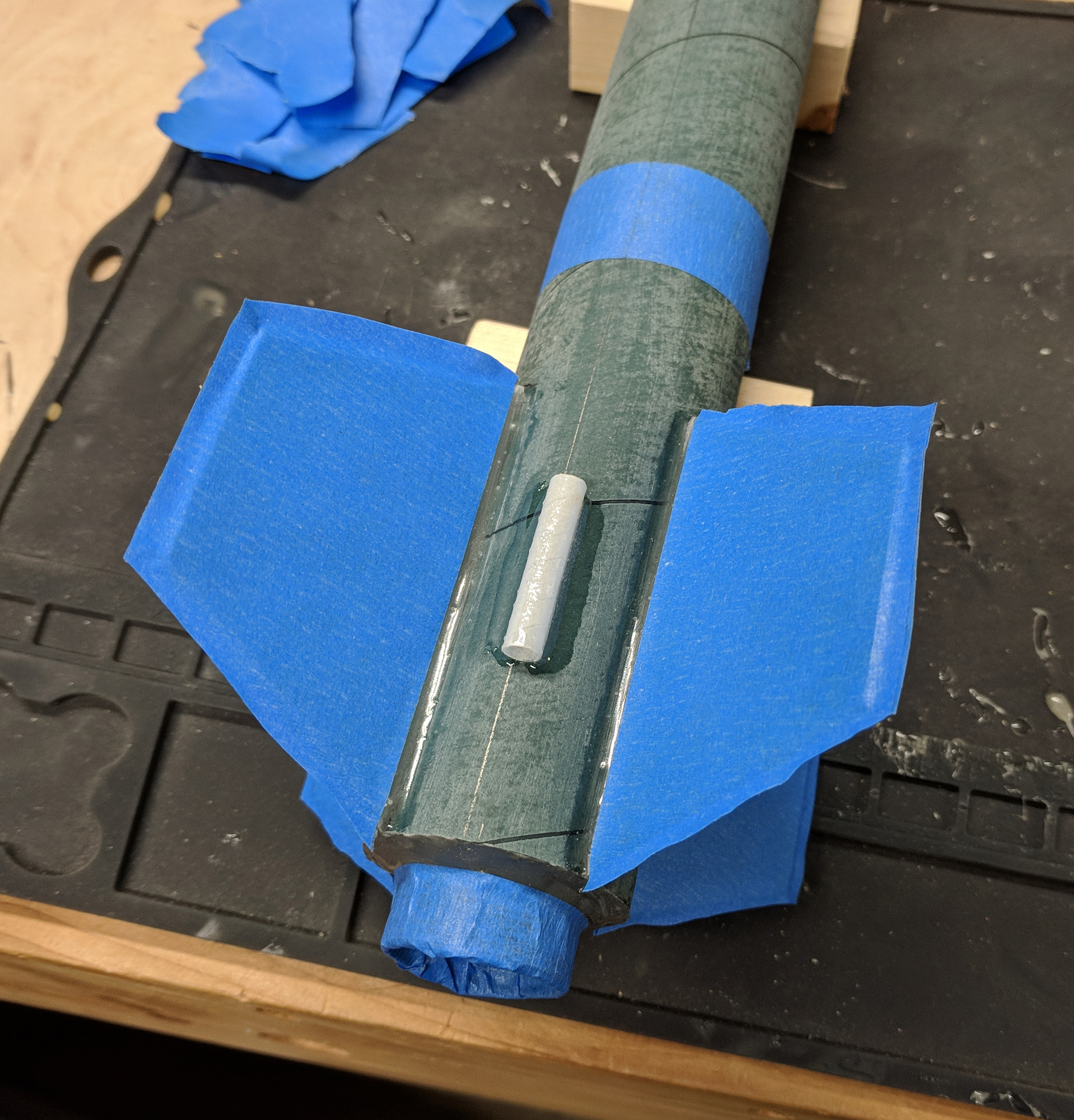
For flexibility, Intrepid 2 has both 3/16" launch lugs and 1010 rail buttons on opposite sides. The launch lugs were aligned with the help of a 3/16" rod and held in place with blue tape while being attached with epoxy, then fillets were added to their sides.
 |  |  |
The rail buttons were added as a modification after the rocket was finished. They are screwed through the blue tube, epoxy applied to the screw threads in the hole and the bottom of the buttom, and an epoxy fillet around the bottom edge of the button. The forward button’s screw was shortened, a wide epoxy fillet was made around the screw hole on the inside, and the inside was sanded smooth to ensure it does not interfere with recovery hardware.
Painting
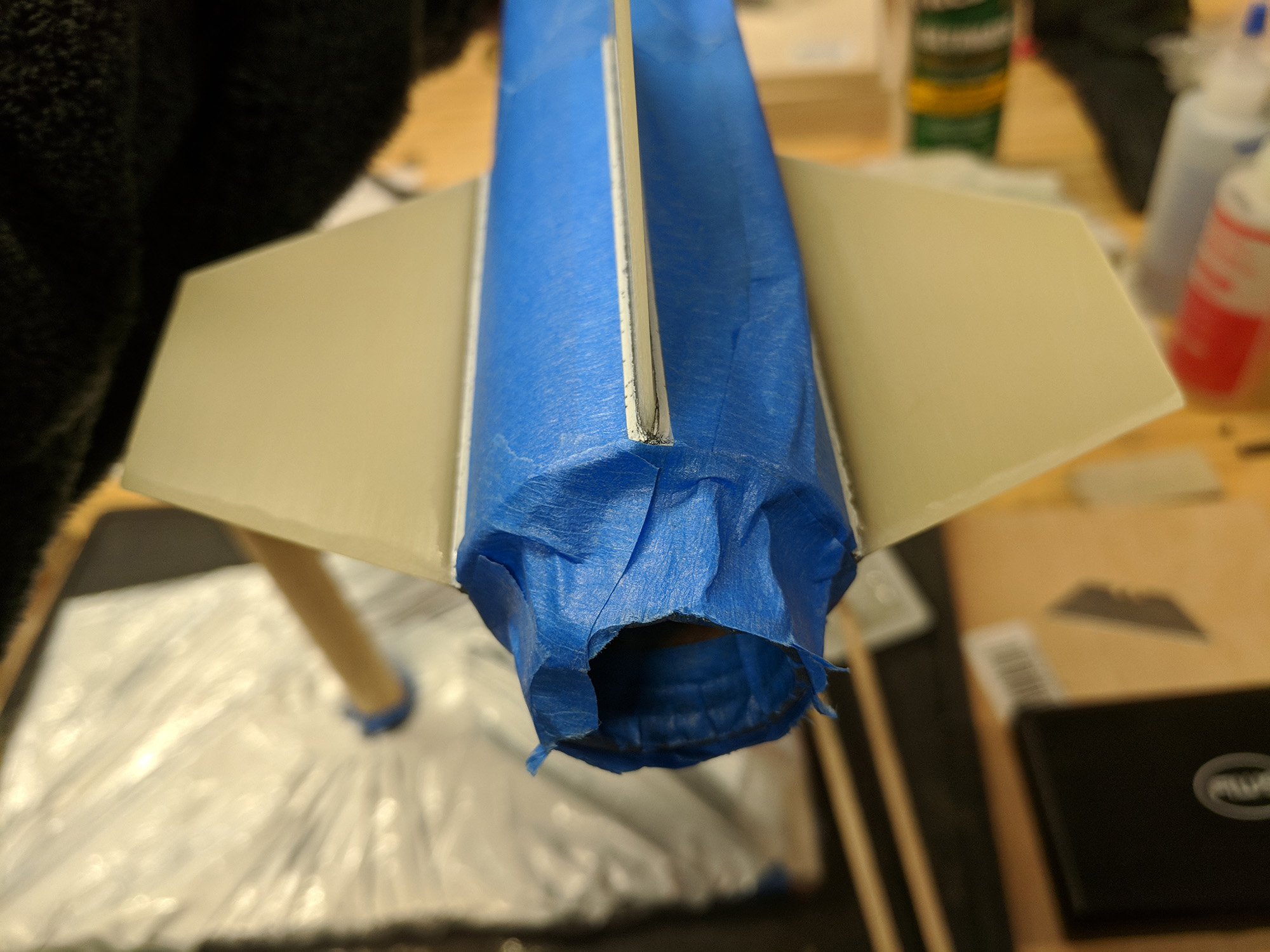
The rocket went through multiple stages of masking and painting. First a base coat of black with primer was applied.
 | 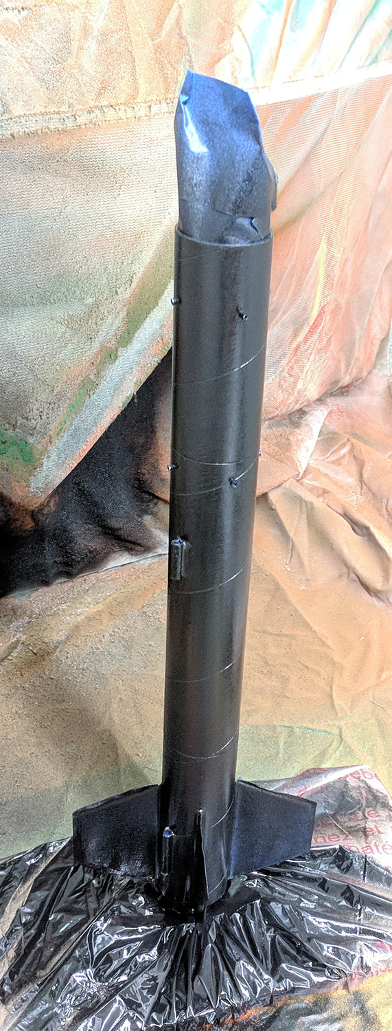 |
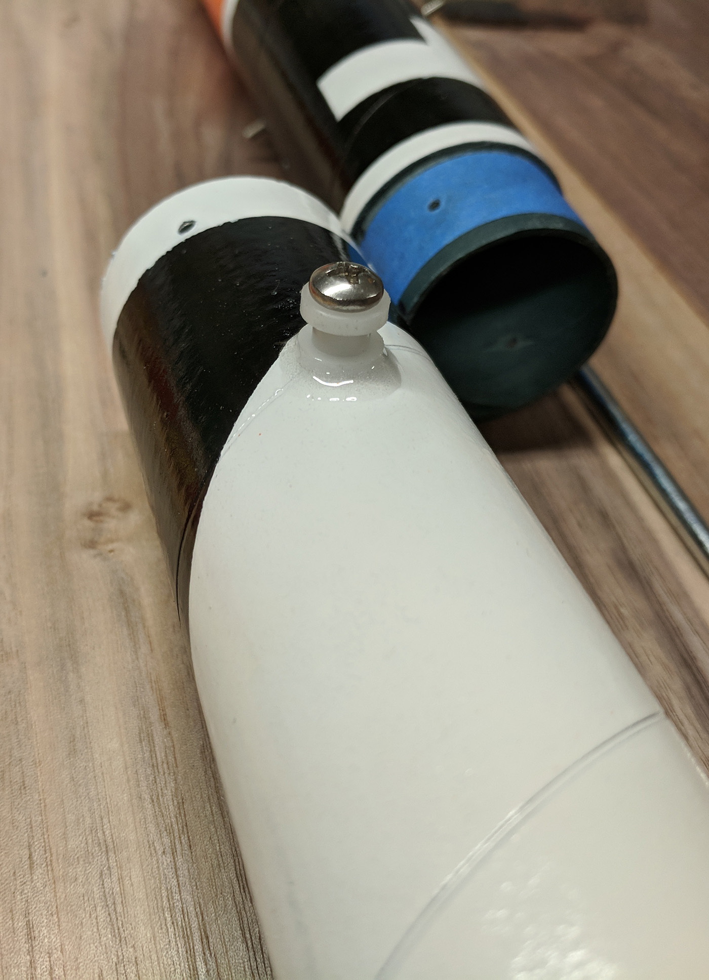
Then it was re-masked for the test pattern and painted with white.
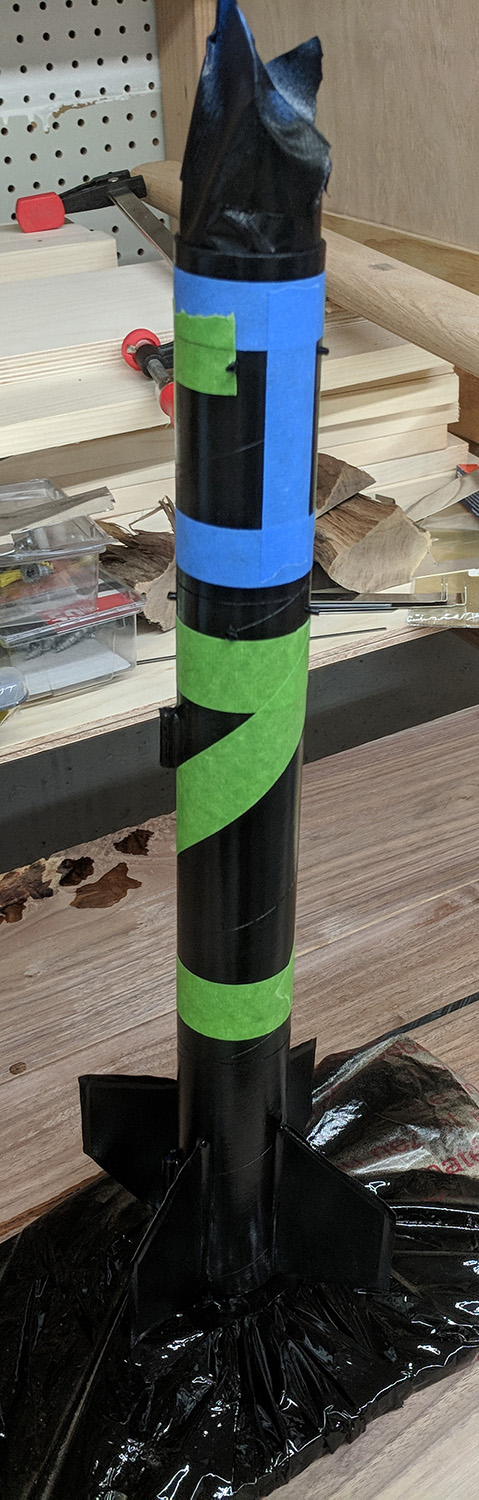 | 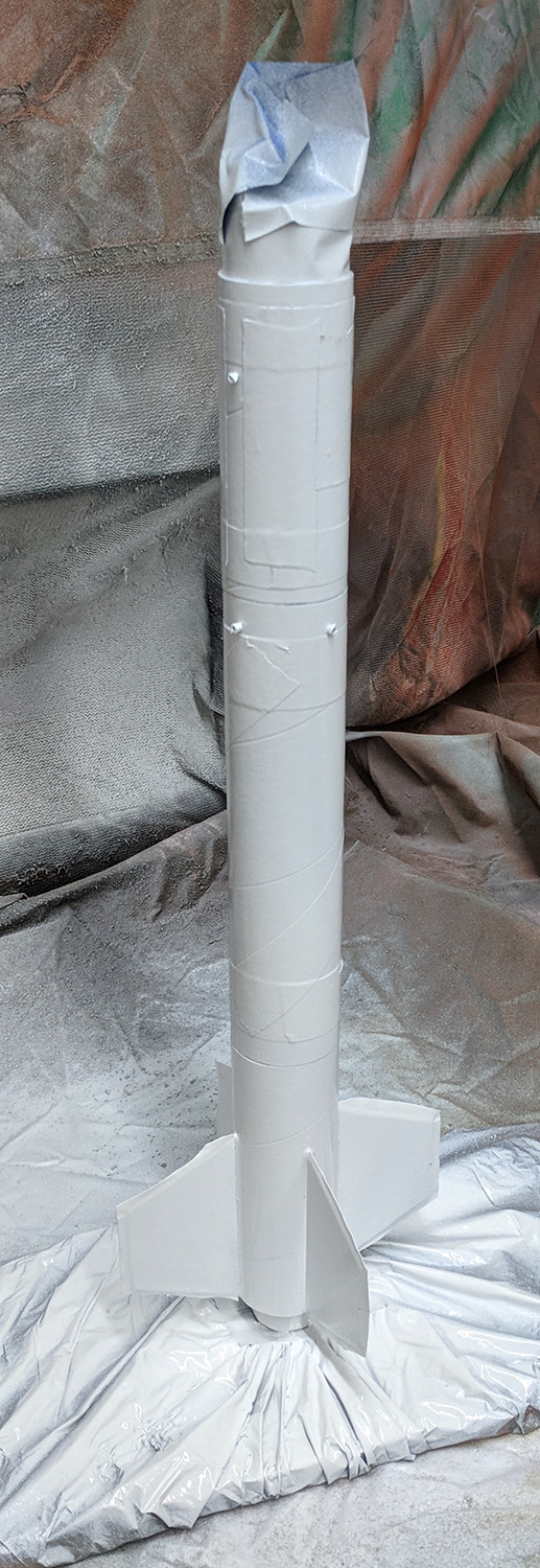 | 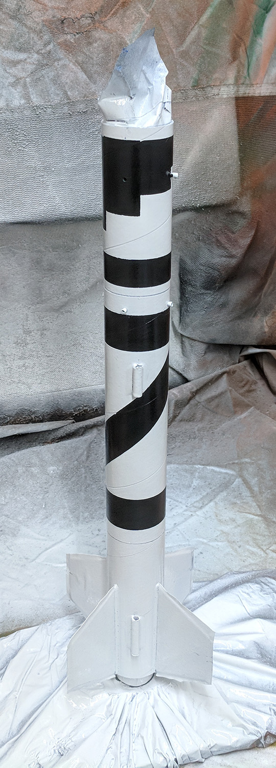 |
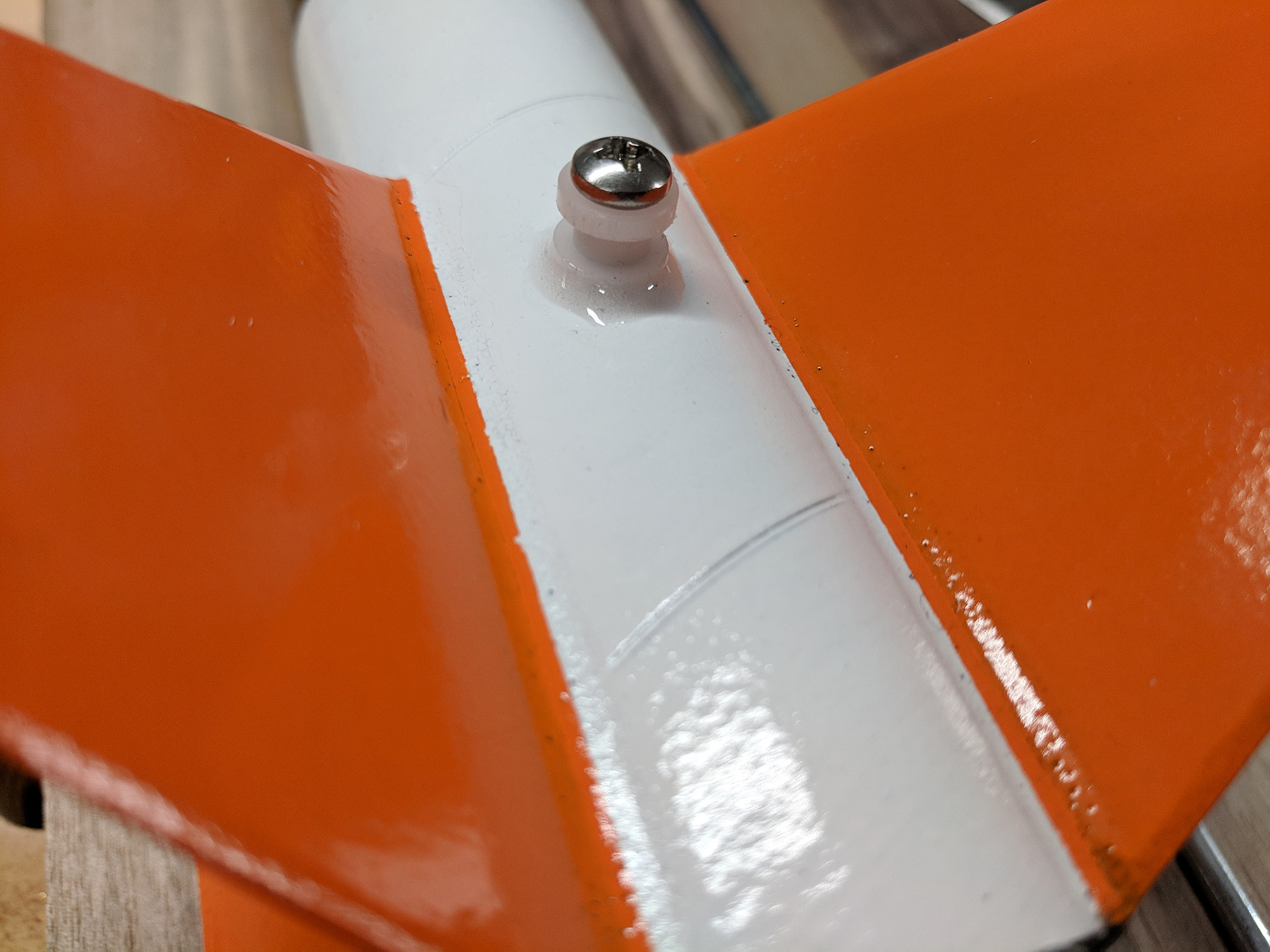
Then re-masked so only the fins were exposed and painted with orange. The nose cone was also painted orange.
 | 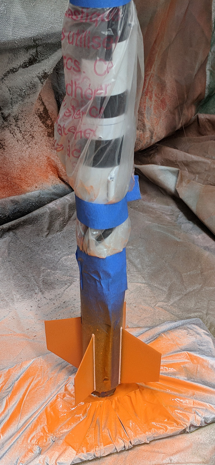 | 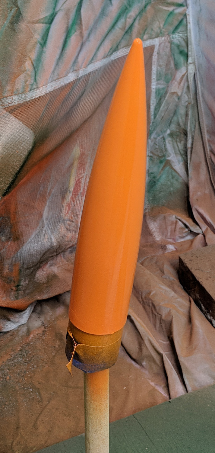 |
Finally, many clear gloss coats were applied to the entire rocket to provide a protective coating.
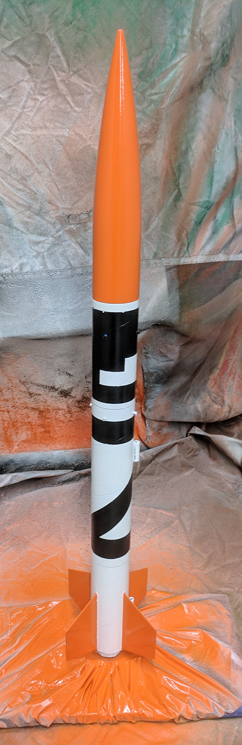 | 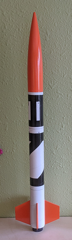 |
Shock cord
The shock cord is 3x the rocket body length (for a total length of 180cm), has #5 safety snap barrel swivels (28lb test) on both ends, and a butteryfly knot loop 1/3 of the way from the forward end for attaching a parachute.
For high-power flights, an alternate shock cord will need to be used. It should have at least #1/0 (80lb test) or larger snap swivels and be 4-5x the rocket body length.
The parachute is attached with a snap swivel to the loop. A nomex sheet is threaded on the aft end of the shock cord. The shock cord’s ends are attached to the eyebolts on the fin can and payload section bulkheads.
 |